Installation Instruction for BRM V-Max Tank
.
| Thank you for trusting into our products. We are trying to work complaint free. For this reason all parts are controlled very precisely before the shipment. Nevertheless, it can occur in exceptions, that there may be complaints. If a part should be damaged, please send back it, we exchange it with reimbursement of the shipping-costs, free of charge. We are basing the legal grounds on our business conditions
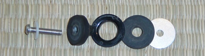
Attention: Maximum torque of all screws at the tank as the Photo from the Part list. No "Burn out" with this Tank |
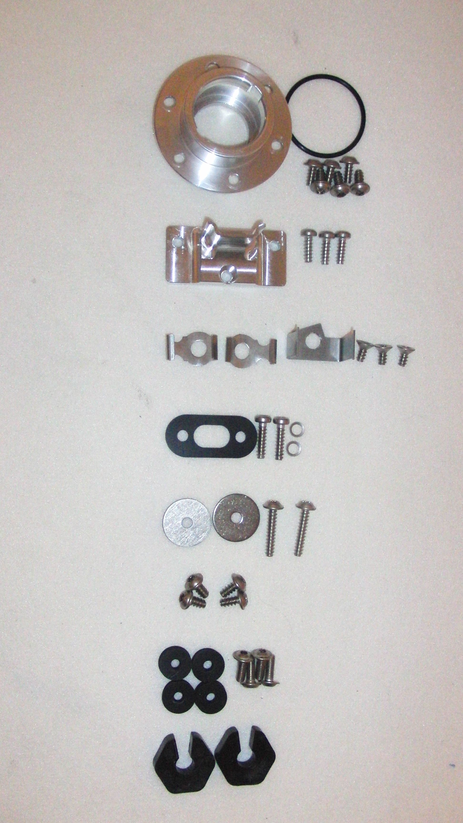 |
Tank Nozzle, O Ring 6xM6x16 4-5 NM/ 3-3,7 LBS
Main Holder 3xM6x20 4-5NM, 3-3,7 LBS
3x retaining plates left/right, fuel filter 3xM6x16 flat head 3-4NM/2,2-3LBS
Reserve switch seal 4-5 NM/ 3-3,7LBS
Holder Top 2xM6x35, 2x washer 4-5NM/ 3-3,7 LBS
Wheel arch Not applicable! No longer necessary and no longer included.
Side caps 8x Rubber 4xM6x16 Lens with flange 5NM/ 3-3,7LBS
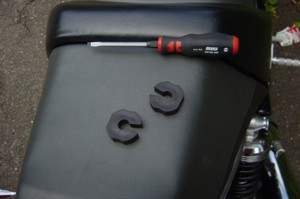
2 Spring travel limiter |
|
|
| If any of the listed parts, despite exact control, are
lacking we kindly ask you to report this to us immediately. We will send these
to you free of charge. Attention: Maximum torque of all screws at the tank as the Photo! Dismantling / Installation 1. Secure Motor cycle by putting it on the main stand. 2. Gasoline is combustible and emits unhealthy vapours. Please provide sufficient ventilation of the area during the mounting and remove each type of naked flame, spark-flight or electric cables, which represent a possible source of danger. 3. Following parts are to be dismantled in this order: 3/1. Drivers and passenger-seat. U-bracket together with rear fender, tail-light and licence-plate. Dismount rear-wheel. Struts left/right. Side covers. |
 |
 |
|
|
|
|
Passenger footrest incl. left side framework-brace
|
|
|
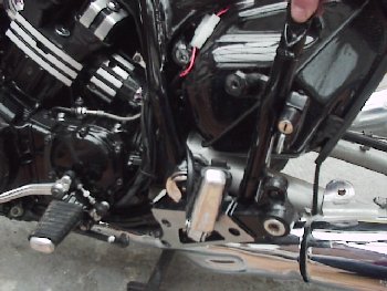
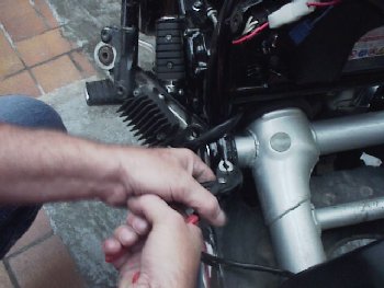
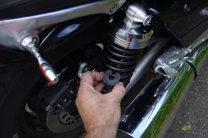
Take out screw on silencer right and left |
|
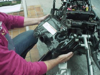
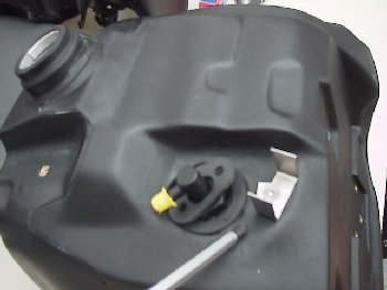
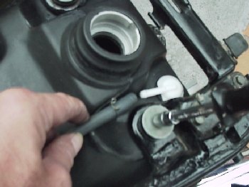
| 3/2. At the tank: |
|
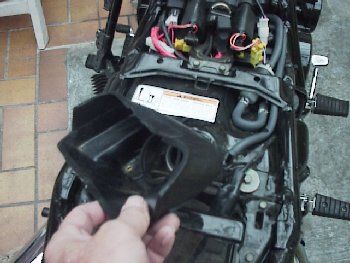
Withdraw the fender |
|
|
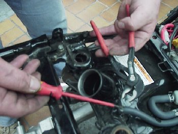
Withdraw the gas-line behind the
gas-filter |
|
|
Withdraw
ventilation-hose |
|
|
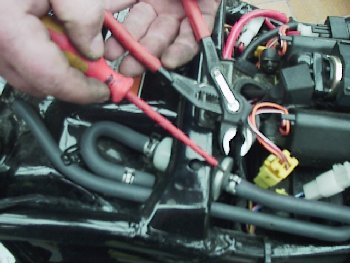
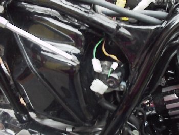
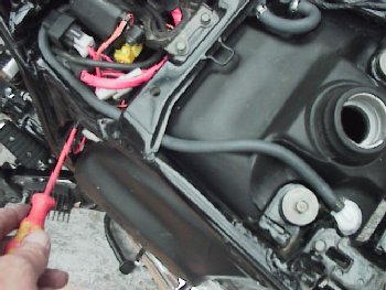
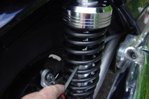
Separate Reserve switch plugs
(right |
|
|
Take off tank-cover |
|
|
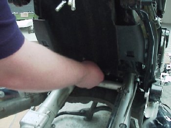
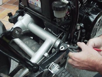
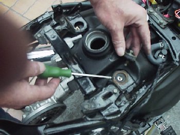
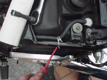
Turn out both upper screws at tank |
|
|
The original-tank can now be taken out to the left as well as to the left behind. |
|
|
|
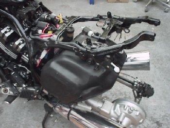
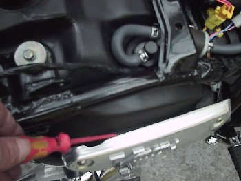
| 3/3. This is only valid at mounting of the
heatshield: Take out the battery and battery-case. The heatshield is put in
between the holder and battery-boxes and fixated with the screws of the
battery-case. Attention The heatshield must be installed if: the series-heatshield of the rear collector is no longer present! If you don't mount the heatshield you run a great risk of fire and explosion! 4. Mounting the Schwabenmax Tank Attention: Maximum torque of all screws at the tank as the Partslist! |
|
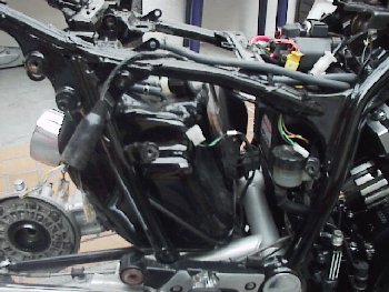
4/1. Aluminum holder in the front,
with enclosed screws / protection-ring. |
|
|
|
|
|
4/2. Mount bent-holders left/right
with enclosed counter-sunk screws. |
|
|
|
|
4/3. Mount U-holder top-right (gas-filter), with enclosed counter-sunk screw and enclosed screws. Mount gas-filter and hose. |
|
|
|
|
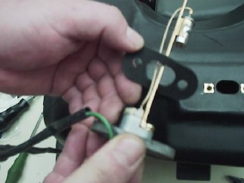
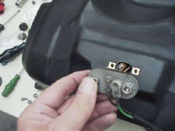
4/4. Mount reserve-switch in the
original-condition with O-ring and with |
|
|
|
|
|
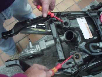
4/5 .1. Left / right bent
carefully the left / right holder straps beneath |
|
|
|
|
|
|
|
|
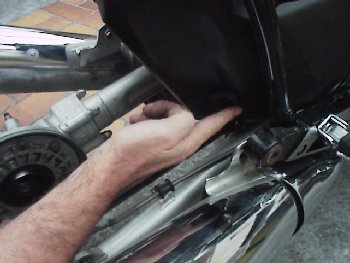
4/6. For easier mounting please grease the holding rubber on the right |
|
|
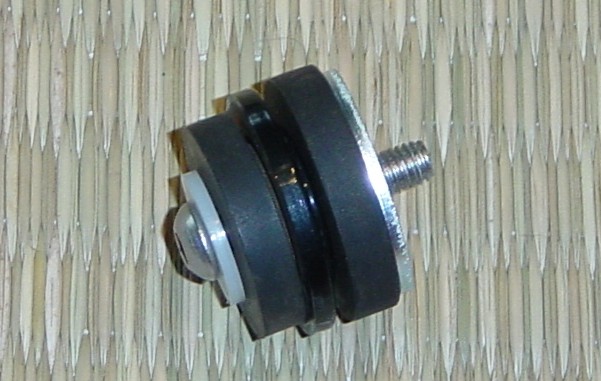
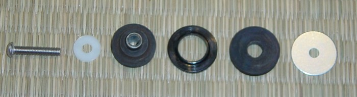
4/7. If the tank is in the right position you insert the enclosed distance-washers at the upper holder. Furthermore you use the original mounting parts (rubbers, washers, screws). " Please do not paste in these screws with Locktite." |
|
 |
|
|
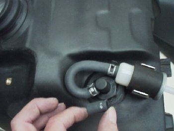
4/8.1. The venting hose will be
put left next to the filler (driving direction). Note: for an easy installation moisten the tube with a drop oil or gasoline. Please connect the tube carefully, the plastic connection can brak relatively easily! |
|
|
|
|
| 4/8.2. Mount all lines and cables and keep an eye
on tightness as well as power supply. 4/9. The screw threads M4 in the wheel base of the tank is for the tank protector (special request). |
|
4/10. Distance side-covers with rubber-washers inner side / screws. |
|
|
|
|
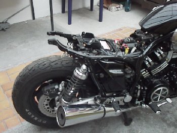
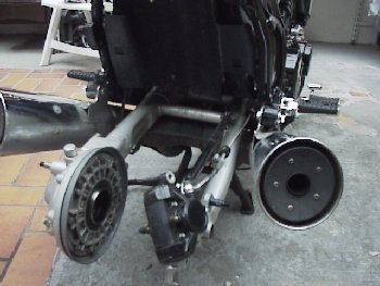
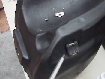
4/12. the stock fender must be
shortened in the |
|
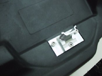
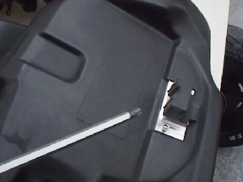
| 4/13. spring deflection clipper instruction in connection with series set of tires and series suspension struts |
 |
 |
 |
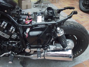
| 4/14. It is necessary to make sure that all electricity wiring, gas hoses as well as brake hose are secured (cable loops) so they won't wear against the tank |
|
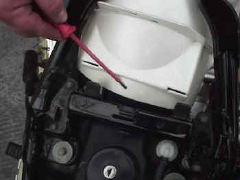
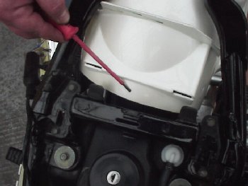
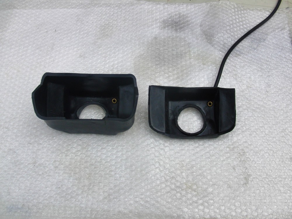
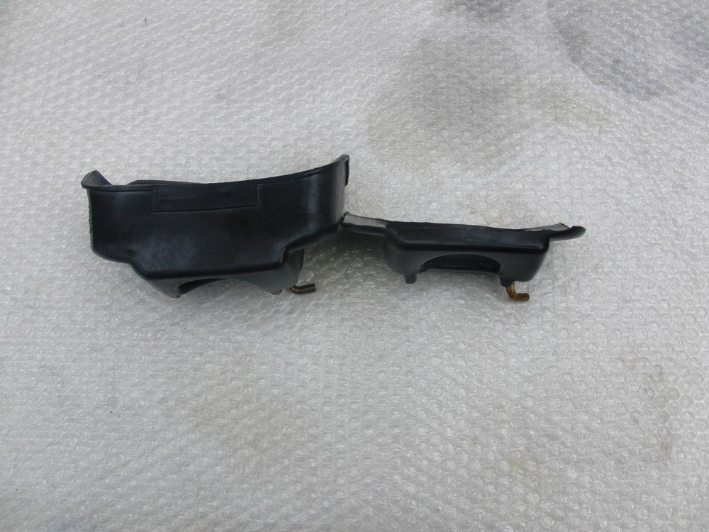
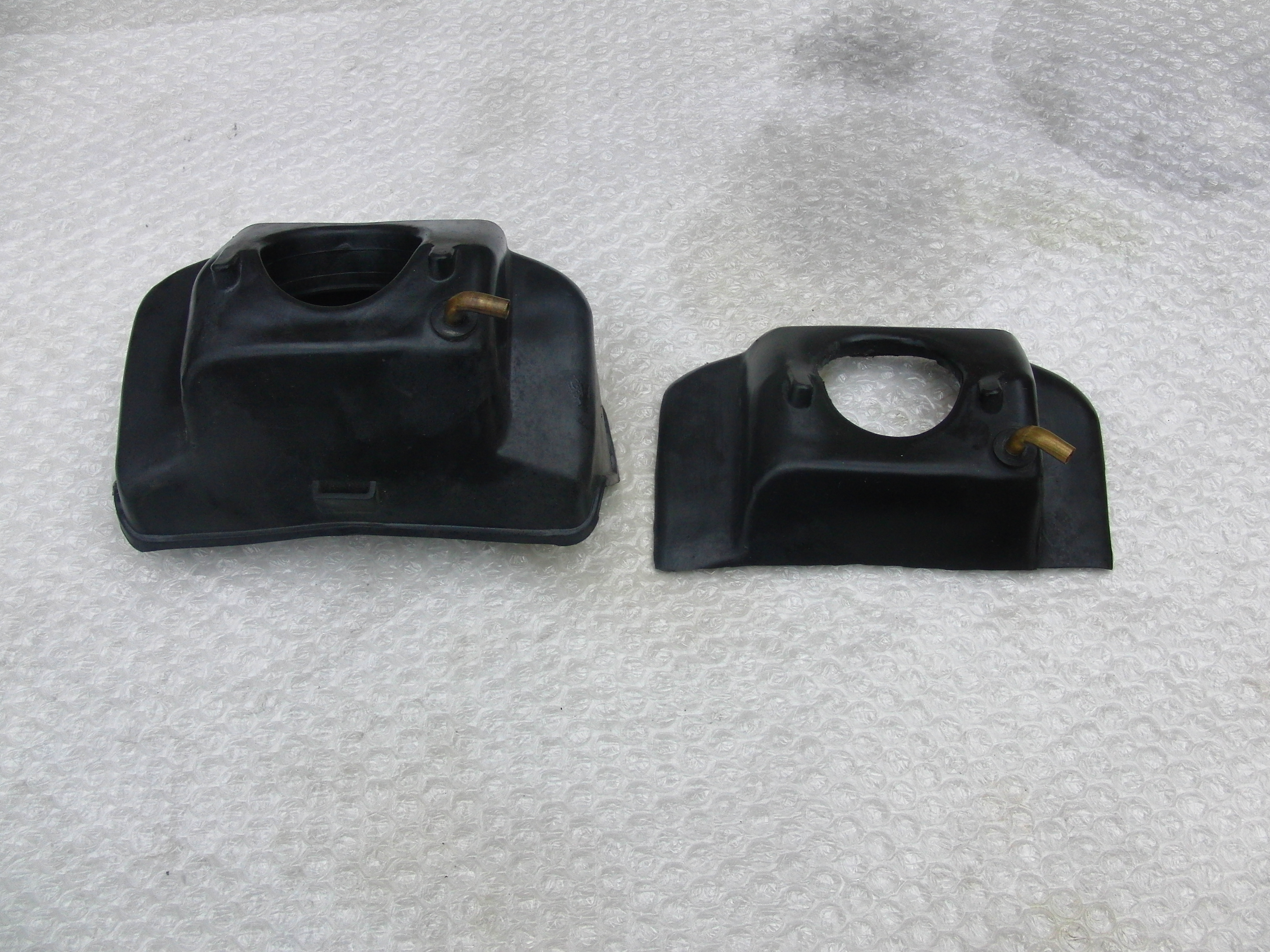
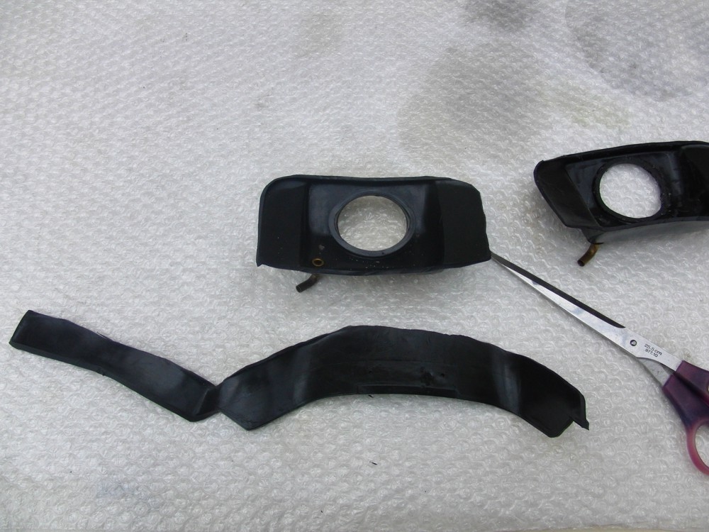
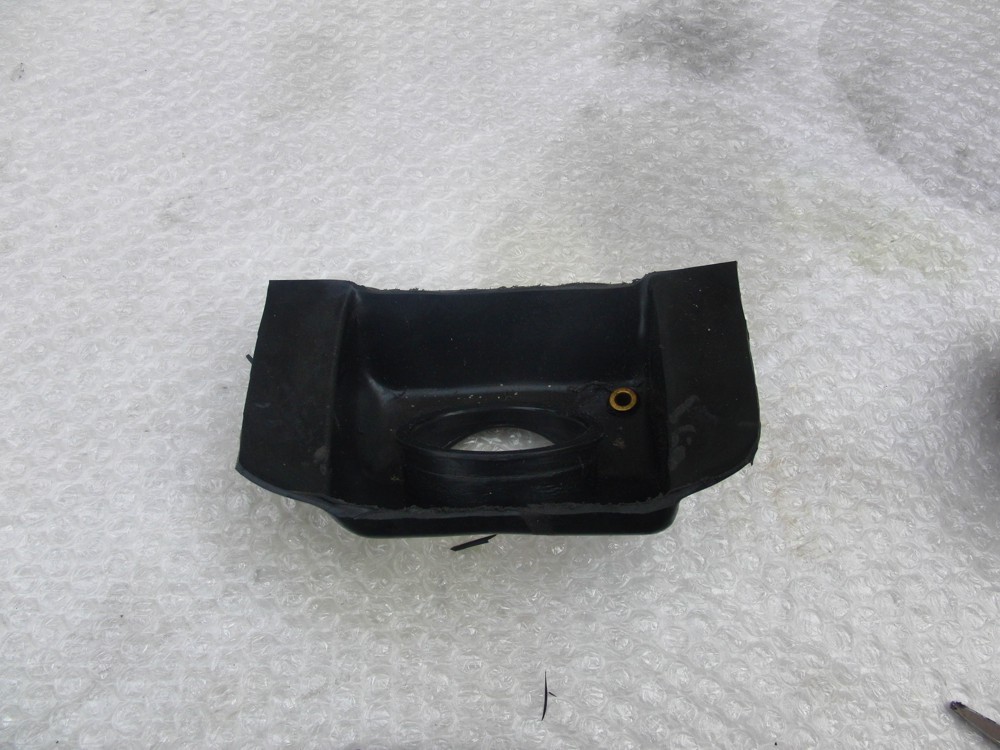
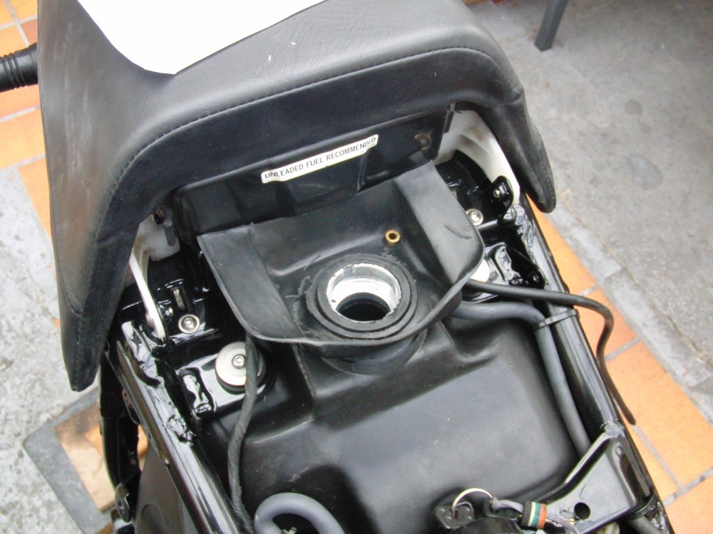
5.On-catch
container/Tankstutzen,
reorganisation
5./1 Photos: Before/after |
 |
 |
 |
 |
 |
|
|
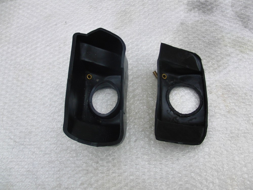
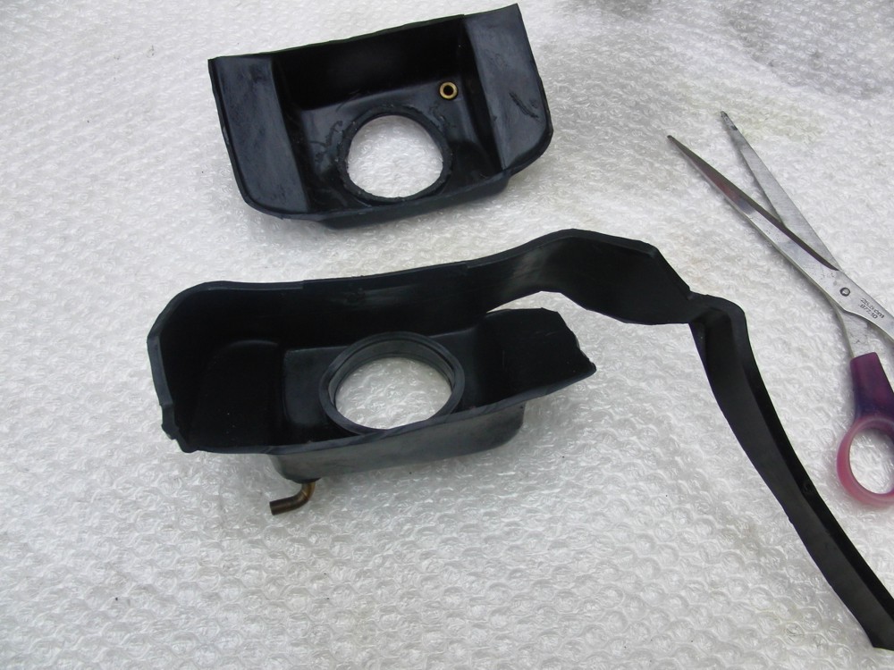
5./ 2.You
need
sharp
scissors
for
the
reorganisation.
See cutting you like on the photos, on the outside around careful and evenly the contour |
 |
 |
 |
|
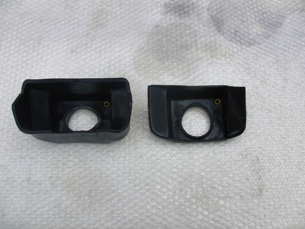
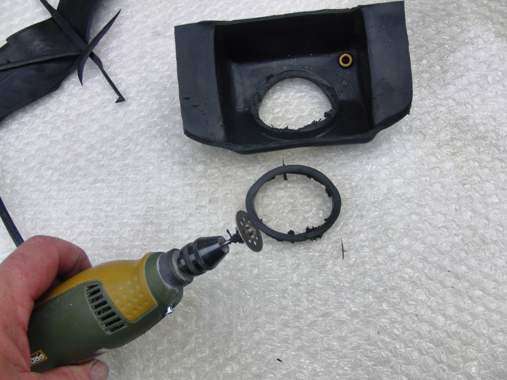
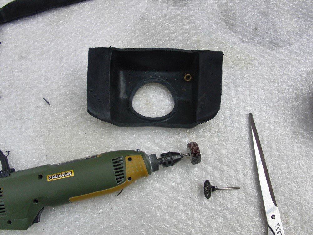
5./2.
As
tool
you
need
a
cutting
plate
or
separating
plate
and
a
fan
grinder.
You need a small grinder of z : b: Proxxon, Dremel, or similar. Below this one trims except for a rest from approx. 6-8 mm with the cutting slice/separating slice cut you. With the fan grinder you smooth all sections evenly. |
 |
 |
|
 |
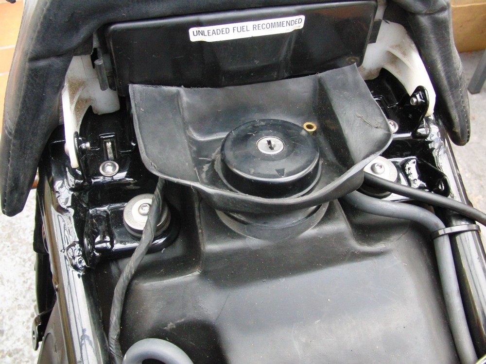 |
| 5./ 3. The filler cap must ready built-inly be easy to put together. |
Additional mounting-, warning- and danger-hints 1. The rear struts must, when fully extended, be at least the length of the series struts (at aftermarket struts). 2. The rear swingarm cannot be higher than the series swingarm in the area below the tank. Aftermarket swingarms of Class, Degget, Fischers as well as the aluminum swingarm of Krueger & Junginger and Otec are all matching. With others, like for example CNC-milled Fischer-swingarms or single-sided swingarms, the distance must be checked. 3. In the rear of the series collectors you find a heatshield. This may not be removed! Aftermarket exhaust systems, for example 4-in-1 or 4-in2 BSMS and others don't have a heatshield. In this case we deliver the relevant part for a small extra charge. See price list. 4. The following rear-wheel rim/tire-combinations may be used: Series, 5,0 x 17-170/60, 5,5 x 17-180/55 and 190/50, 6,0 x 1, however, with 6,0J-rims the swingarm must be set to the most left (offset). Theoretically, rims/tires 5 XS 18J 170/60 will also fit. These have the same dimensions as the series wheels. This must be clarified at the time of the order. 5. As mentioned before the tank will fit without any alterations of the framework, however the rear fender / mudguard must be shortened for aprox. 3 cm at your own costs. You won't need the series plastic-covers at the rear-wheel. With other seats, for example tail pieces by Big Bike or similar, the place-circumstances must be clarified at the time of the ordered. The tank filler is on series-level. 6. The series tank-cap, holding-rubber, gas-filters etc. ar re-used. 7. Technical description: Manufacture in the rotation-glaze-procedure after DIN 16901,160. Used material VEPE, smooth non paintable surface. Heat resistant up to 85 degrees Celsius, melting point at 120 degree Celsius. Comment: maximum temperature reached in real test / critical area 60 degree Celsius. Content approximately 19850 ccms incl. 2,7 l reserve after completed expansion. The used material VEPE will extend after filling with gas on the outside. After approximately 4-6 hours for about approximately 300 ccms. The extension lies in the further in the median value with 1,74% after 30 days and approximately 2% after 1 year. The tank then remains in this form. This expansion benefits the volume. The stated value of approximately 19850 ccms corresponds to the tank-content after 30 days with our used reverence tanks. Of course, this extension was taken into account on the model and tool-construction. This consequently also guarantees that the tank after conclusion of its expansion still can easily be removed and installed. 8. Attention: In order to exclude possible danger-sources, the buyer is committed to store this instruction and to hand over with sale of the motorcycle or the parts to the new owner. For damages that take place due to improper mounting we will take no liability. 9. It is absolutely necessary to make sure that no other parts of the motorcycle can rub against the tank. This could lead to a tank-leak and fire. 10. No Burnouts with this tank. |
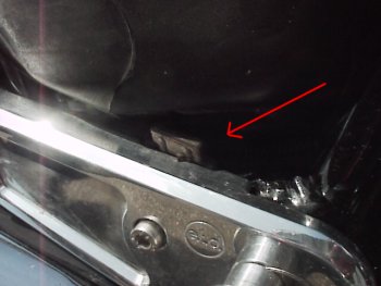
Pay particular attention to the following
areas:
|
| Assemble With application of the series rear fender / mudguard it must be shortened in the area of the tank by about 30 mm. Here you must look out for enough distance (approximately 10mm). Furthermore all parts must be mounted in reverse order of the dismantling. German TUeV The use of this part in public must be approved and written at buyers costs into the motor vehicle-papers of TUeV. With not-enrollment, the licence of the motor vehicle ix extinct. Heed the rules of your country please. If you have any questions please contact us. We wish you good trips and much fun with your V-Max |