|
|
Schwabenmax® ServiceseitenTel: (0049) 07164 9151633 VMAX ab Baujahr 2009 - RP21 Tank 21,5 and
24,5 litres
Set up the motorcycle safely so that it cannot fall over!
Mountingtime 6-8 hours.
|
|
|
Schwabenmax® ServiceseitenTel: (0049) 07164 9151633 VMAX ab Baujahr 2009 - RP21 Tank 21,5 and
24,5 litres
Set up the motorcycle safely so that it cannot fall over!
Mountingtime 6-8 hours.
|
|
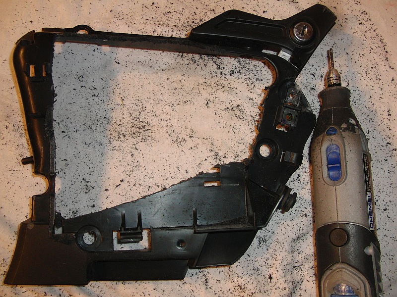
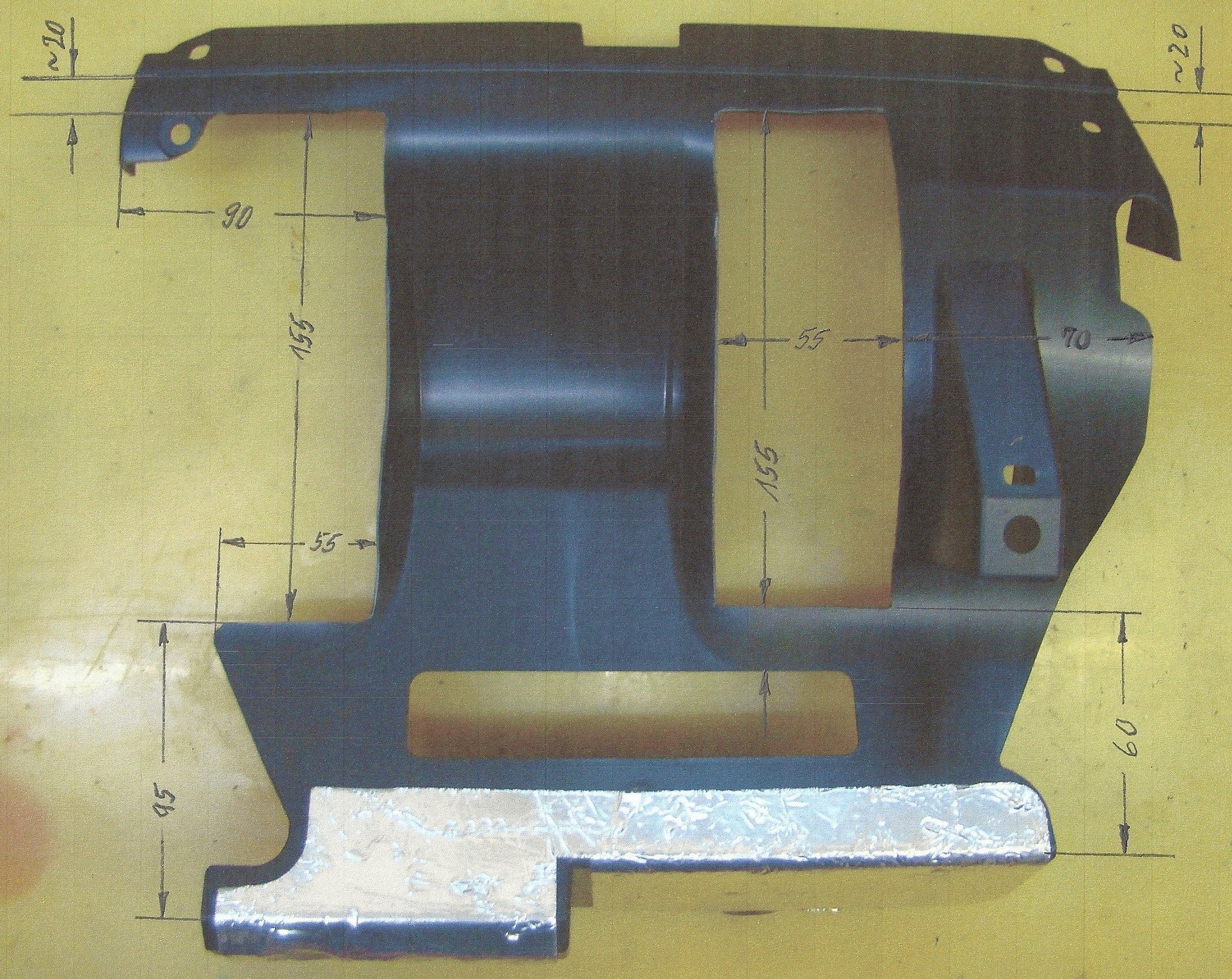
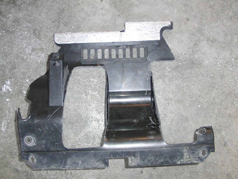
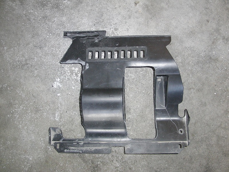
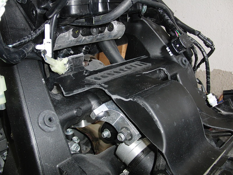
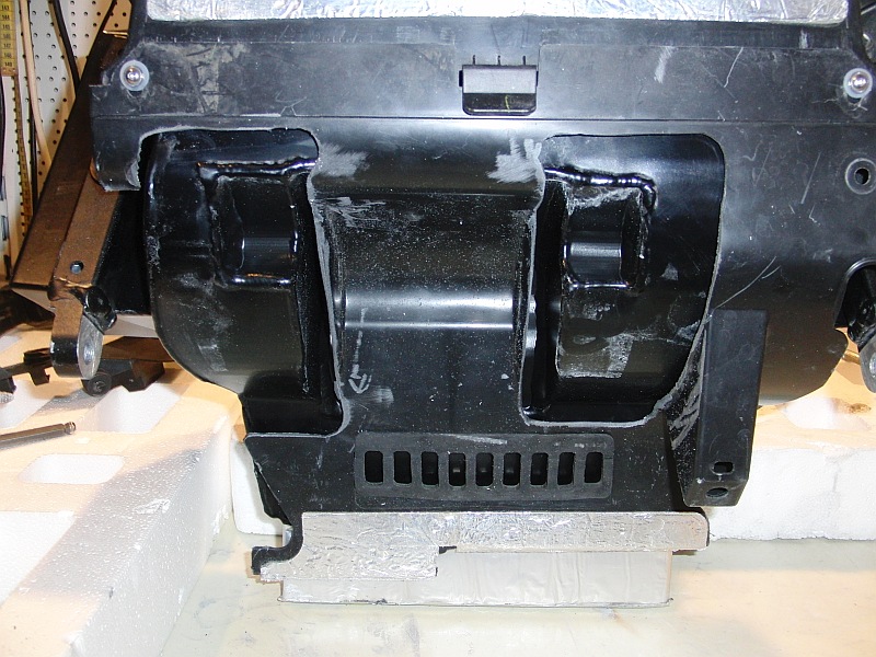
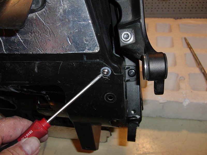
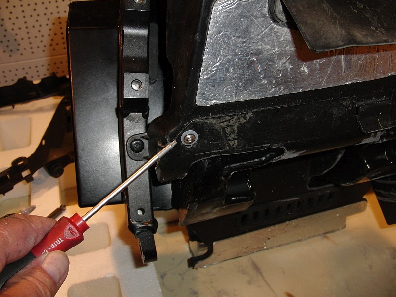
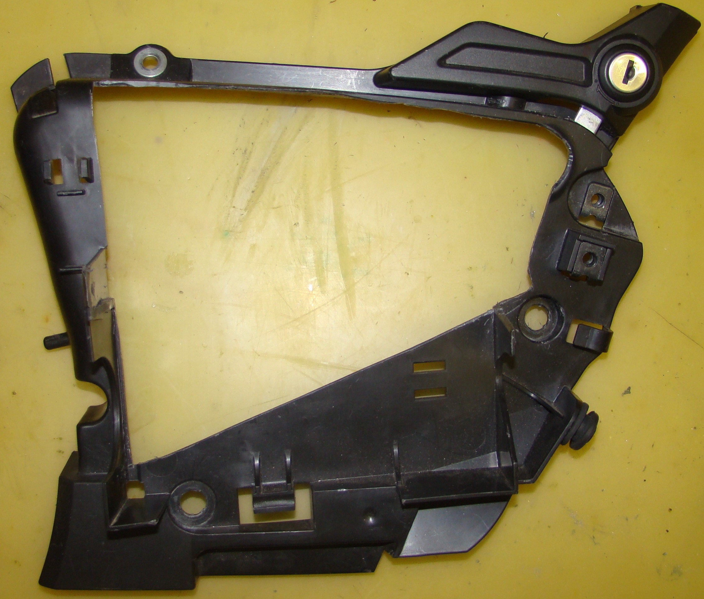
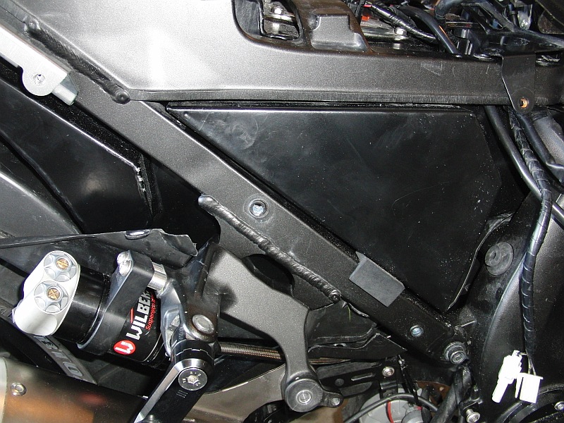
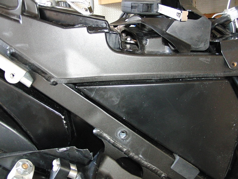
Fig. 1 -4 Cut out underbody, e.g. with a Dremel or similar tool
|
 |
 |
 |
 |
|
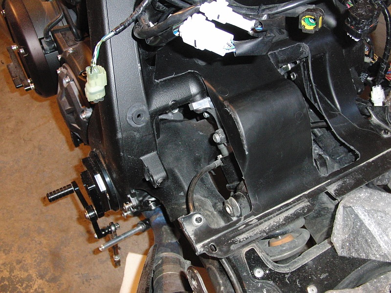
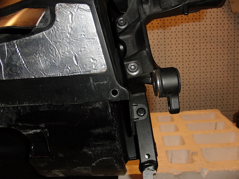
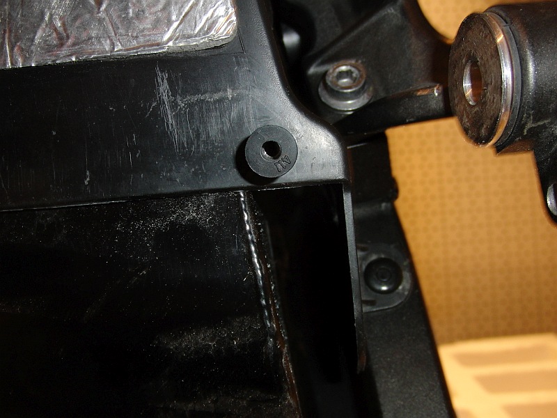
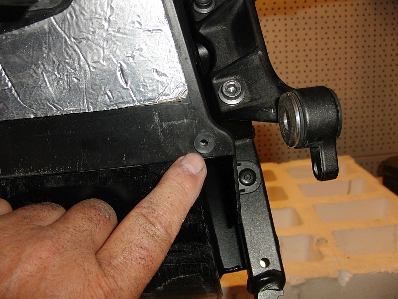
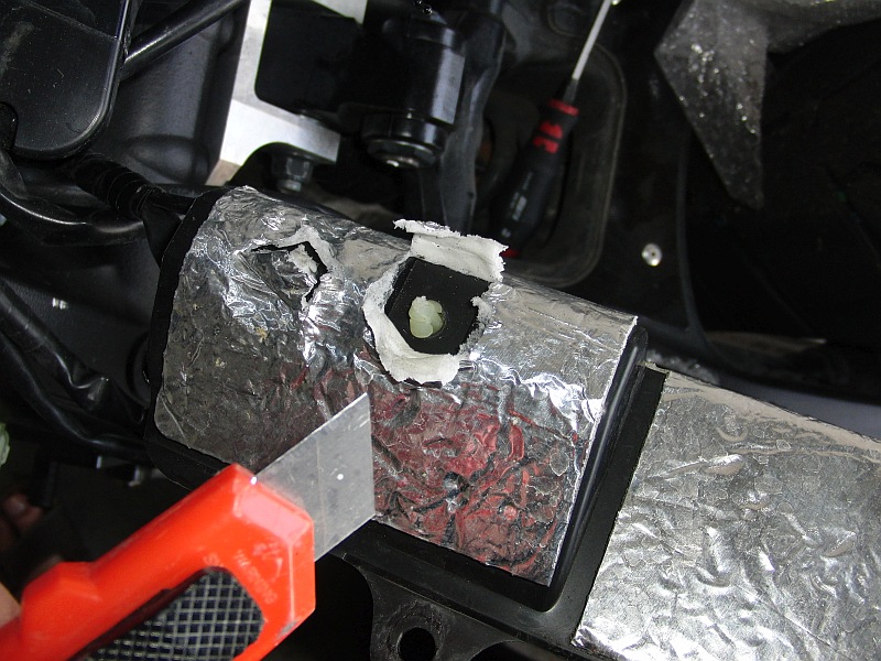
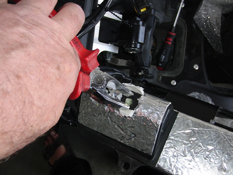
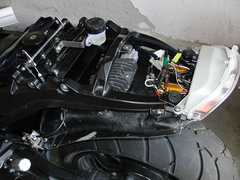
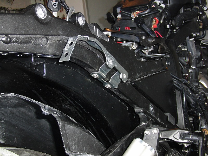
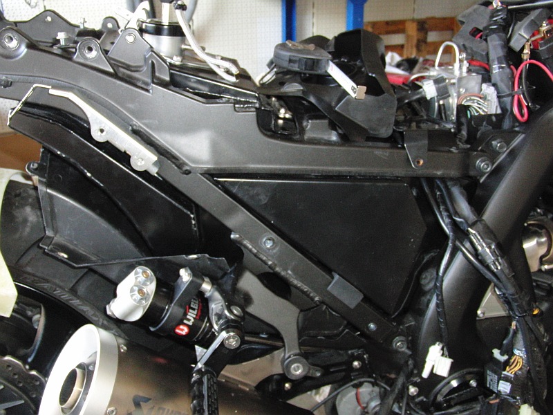
Plastik Vorn/ Plastic front Fig. 5 -8 Cut out the underbody
using the suspension strut. |
 |
 |
 |
 |
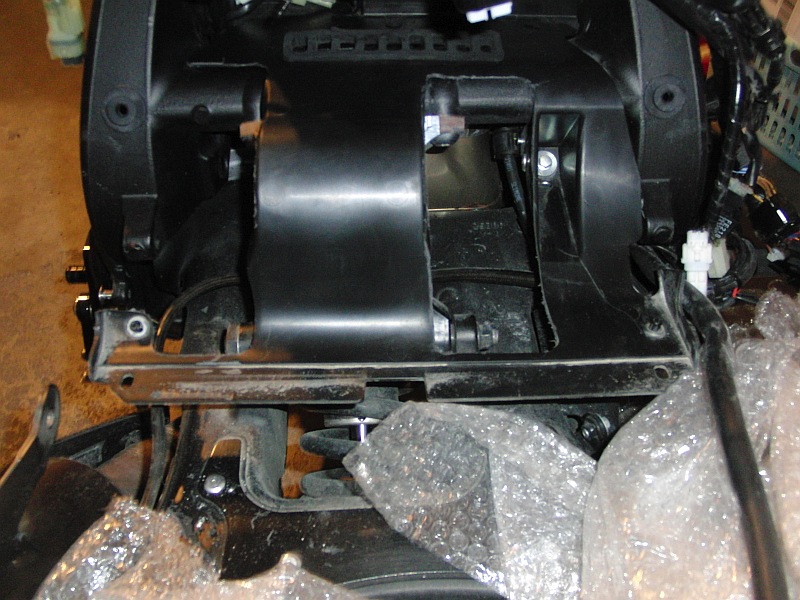
| Picture 9-13 |
 |
 |
 |
 |
 |
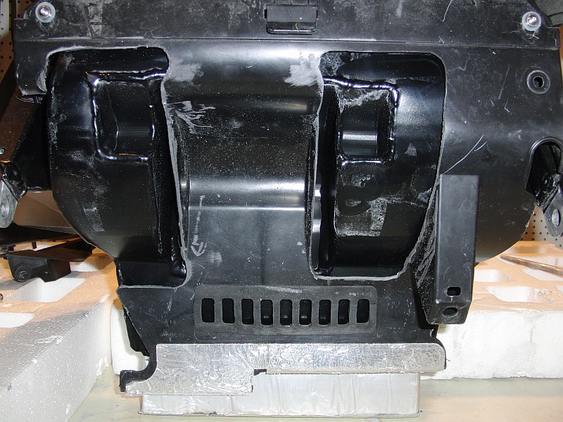
| Picture 14 - 15 -16 |
 |
 |
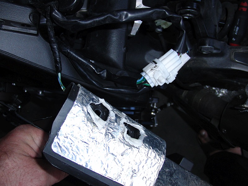 |
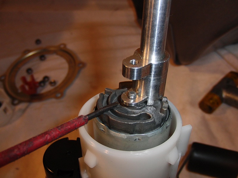
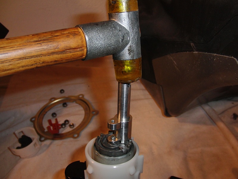
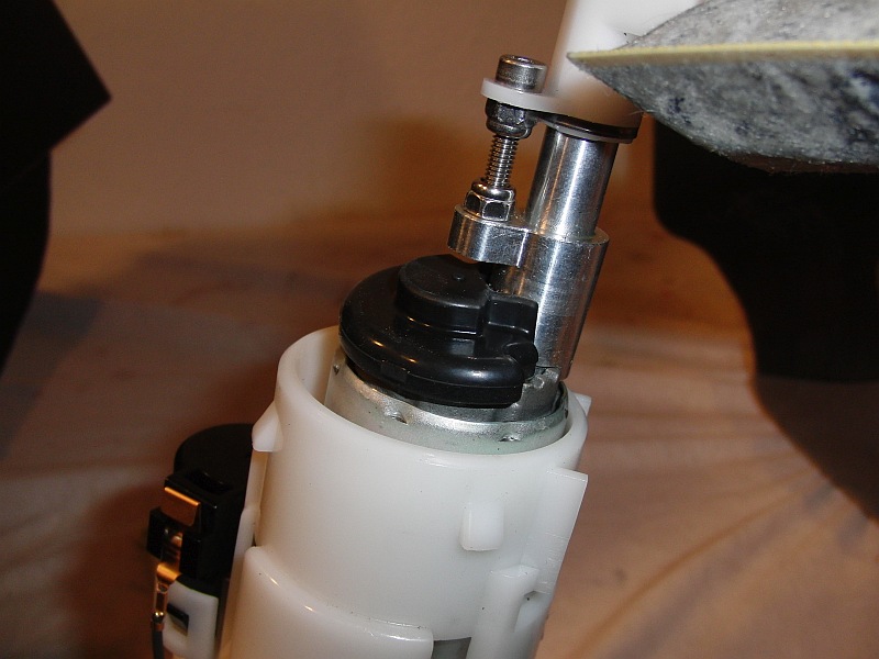
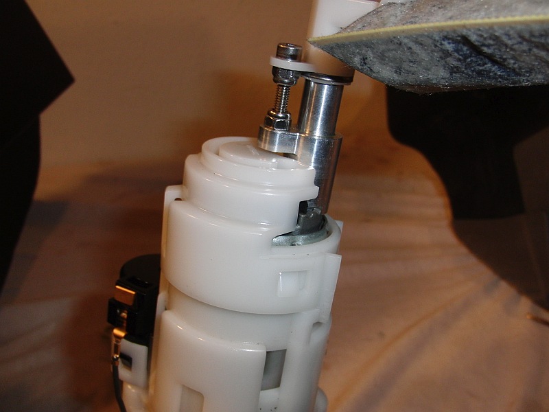
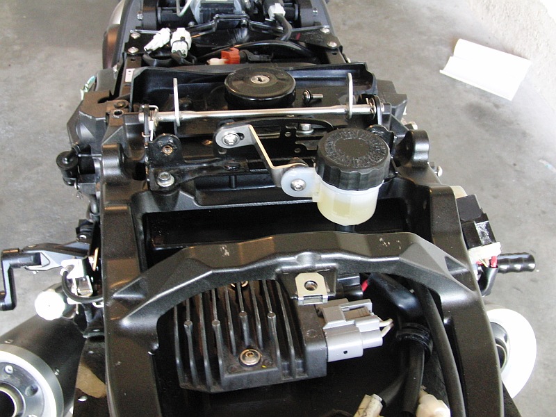
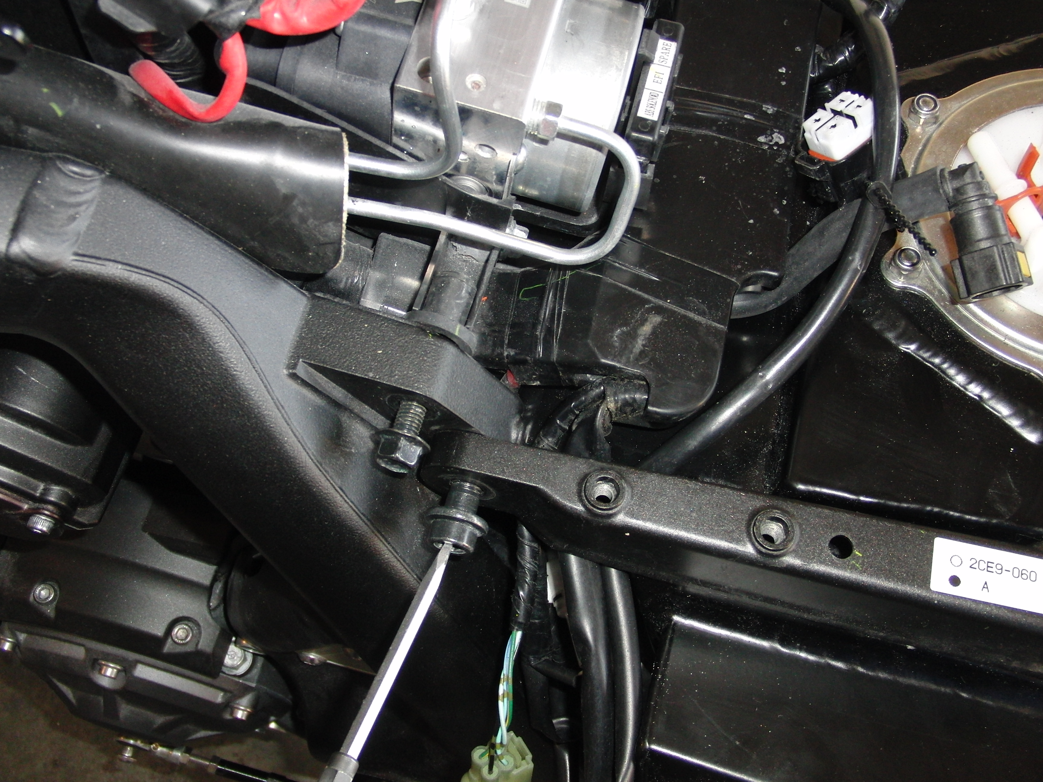
| Fuel Pump/Petrol Pump |
 |
 |
 |
 |
 |
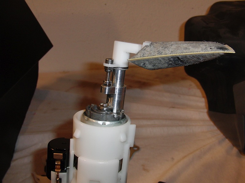
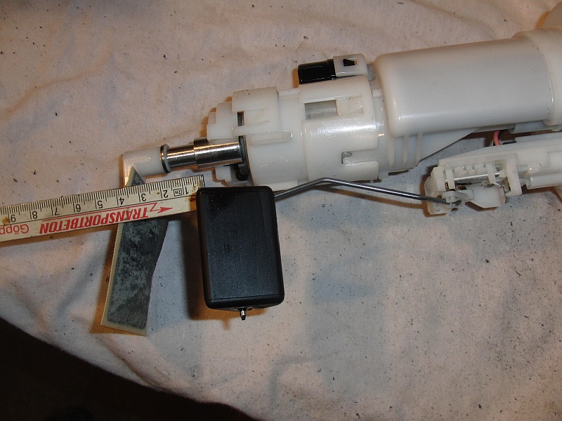
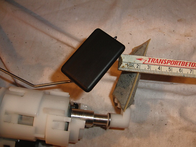
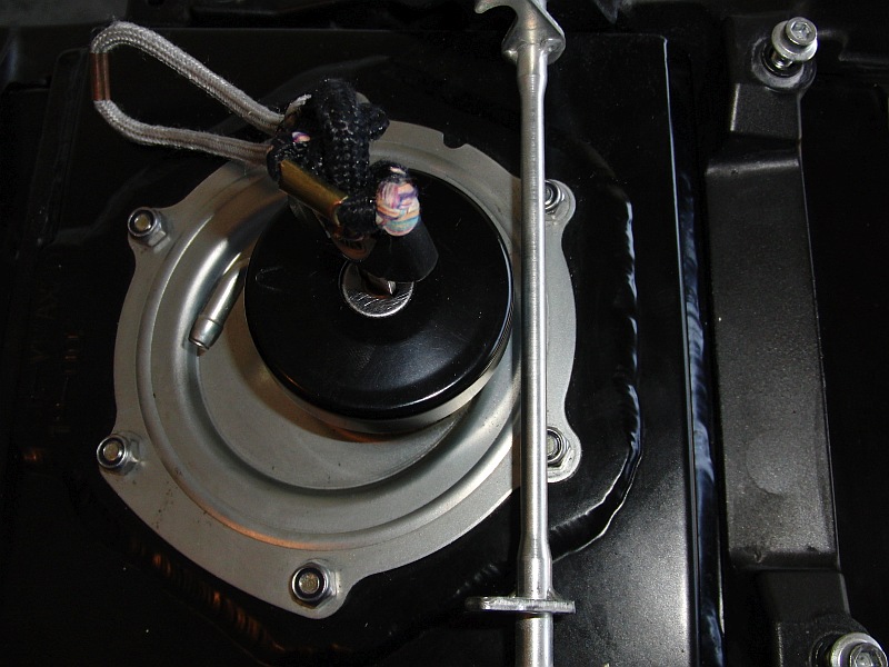
| Float Stand The float stand can, but does not have to, carefully bend the boom by hand. until the specified dimension is reached. If the float is left in series condition, the reserve indication is very inaccurate ! Fig. 22-23 |
 |
 |
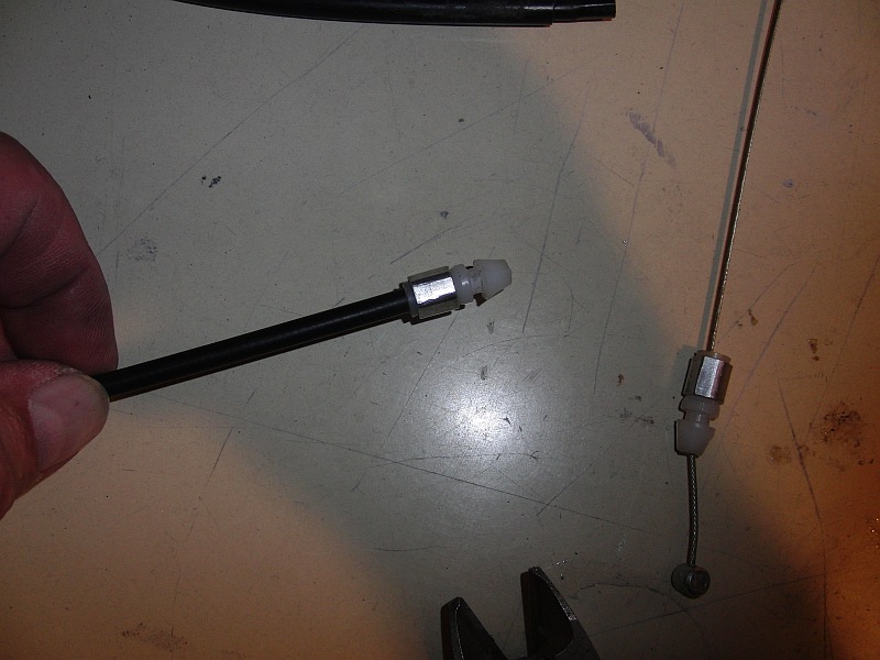
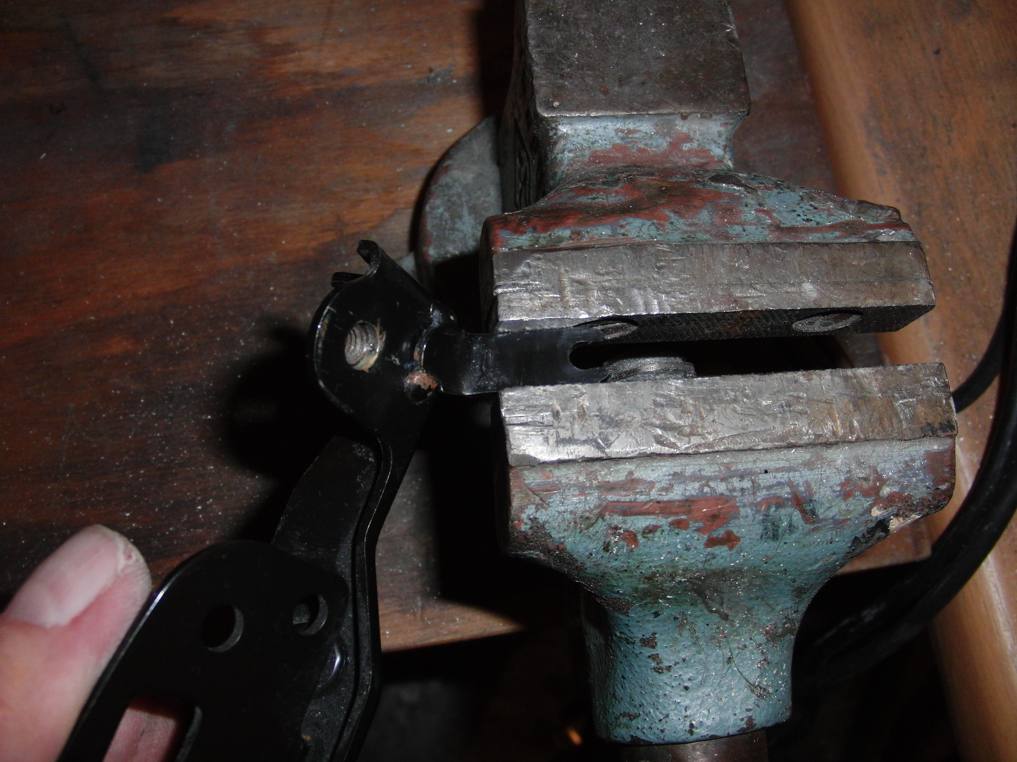
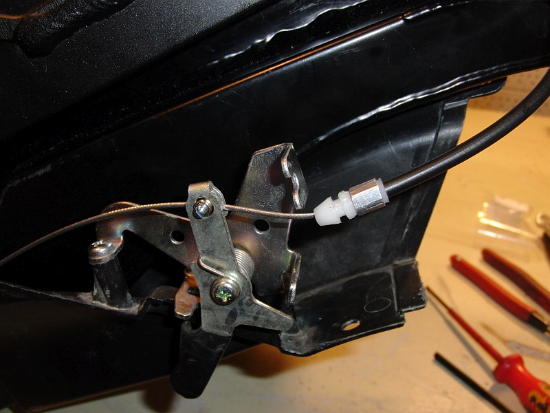
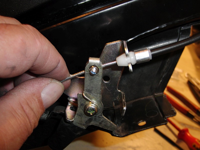
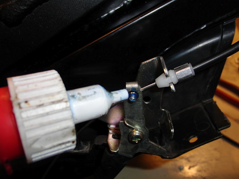
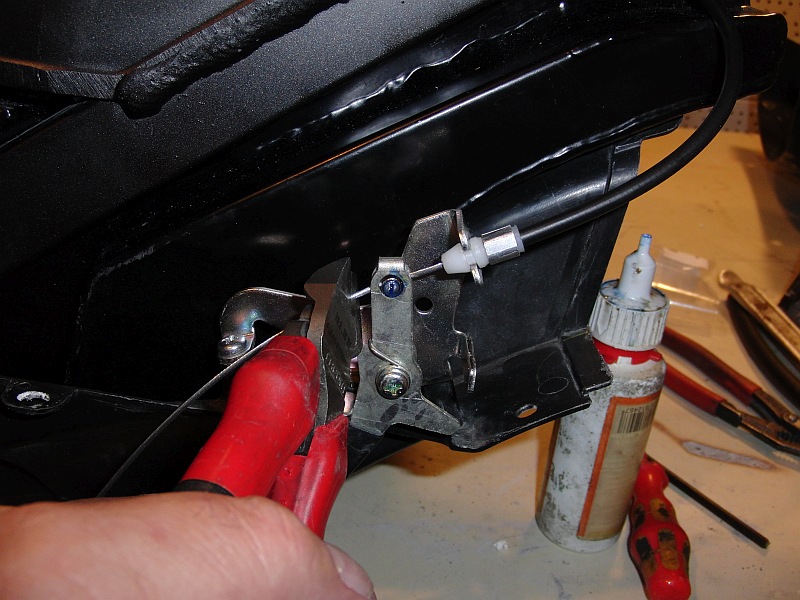
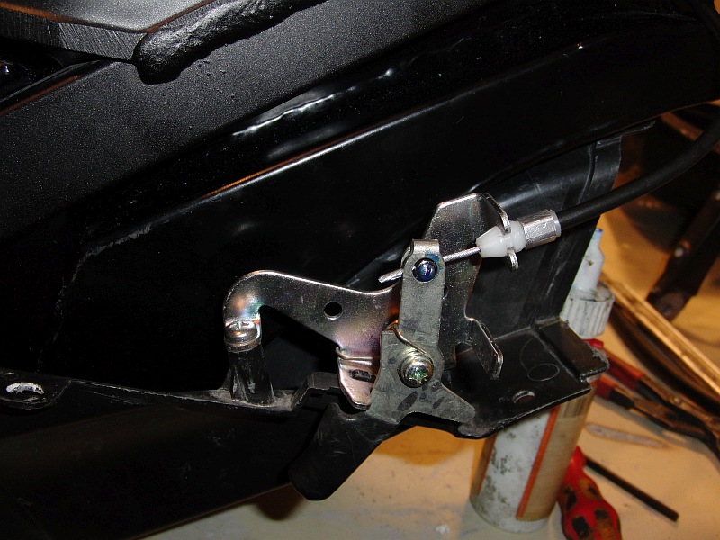
| Seat lock cable. |
 |
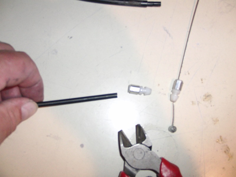 |
| Bend the holder rope pull outwards. |
 |
 |
 |
 |
 |
 |
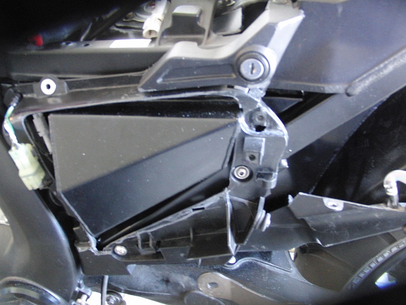
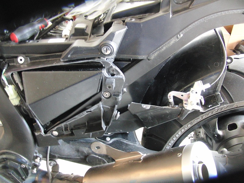
| Left side cut out plastic fairing to fit Picture 31-34
|
 |
 |
|
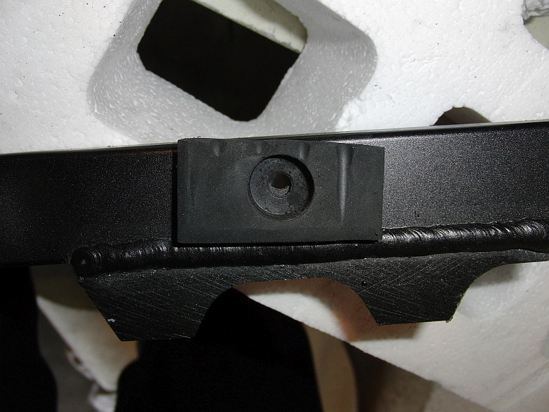
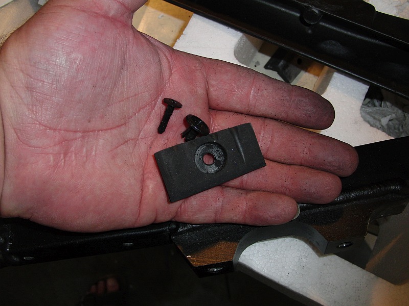
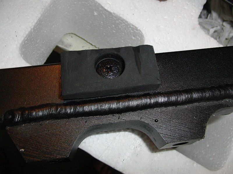
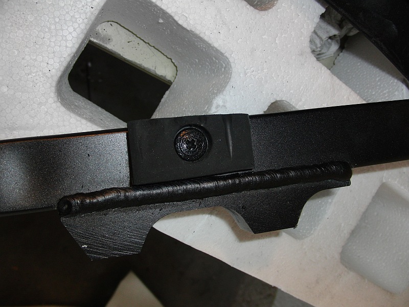
| Mounting overflow - Fig. 25 |
 |
|
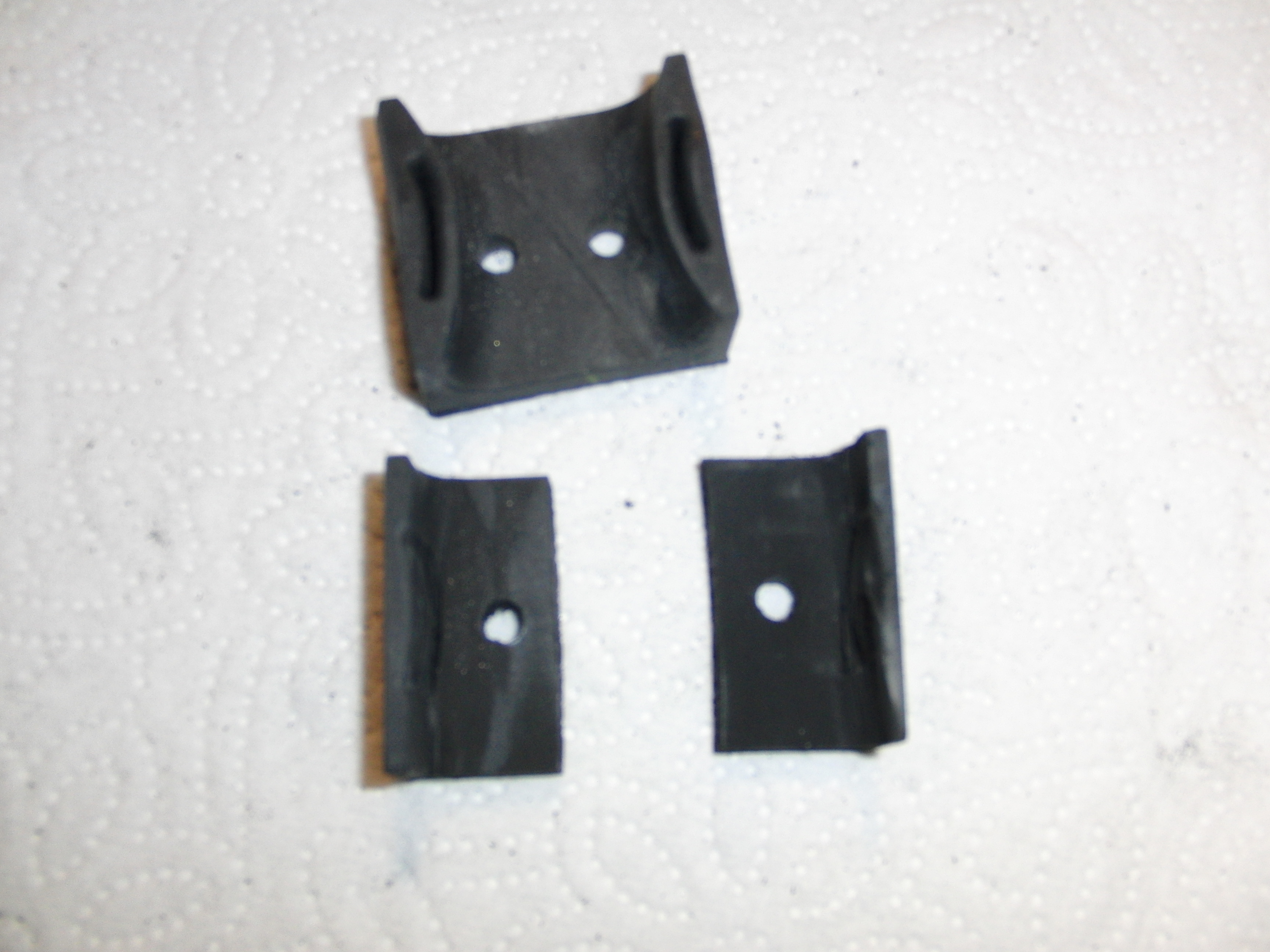
Use of the original rubber
distances. |
 |
 |
 |
|
|
 |
 |
 |
 |
 |
|
|
 |
|
|
|
brake reservoir |
 |
 |
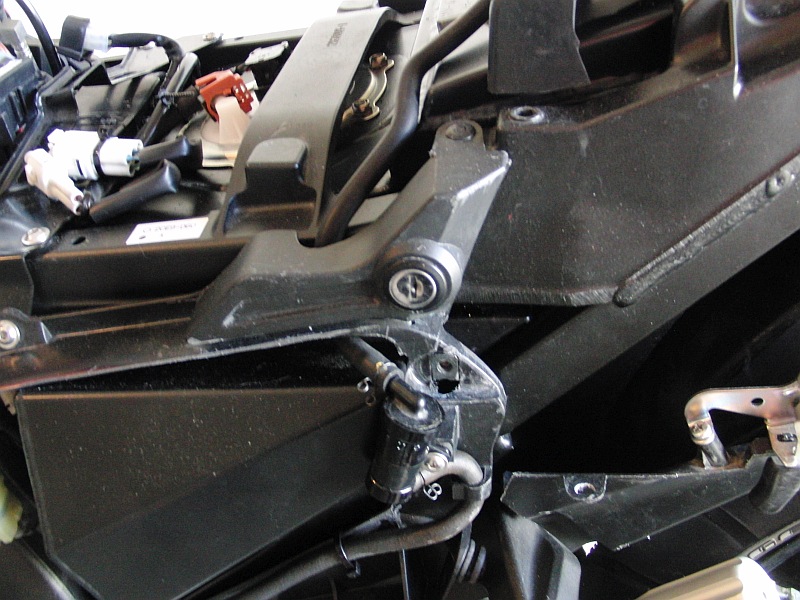
| Mounting Position Picture 48 - 49 - 50- 51 |
 |
 |
 |
 |
|
|
| Screw the frame on at the top |
 |